This week: Testing and data acquisition

It’s a few weeks after the 2013 competition, and we are already on our way to designing the 2014 car.  We held elections and all the new system leads are designated.  This coming season, I will be in charge of the steering system, as well as take on the new position of technical director.

The technical director has two main responsibilities: keeping the full car Solidworks model and being in charge of the team’s new data acquisition system.  Last year’s full CAD model is shown below.

Baja Car

Having an entire model of the car helps immensely with the integration of all the subsystems.  Being able to measure a distance in the computer model, then use that to locate your parts rather than some arbitrary placement means that we will actually build the car that we designed.  It also helps us figure out issues with packaging (fitting all the parts in) early, while still in the design phase.  In the past, these sorts of issues have been solved with on the spot design changes, which often result in a “thrown together” looking car.

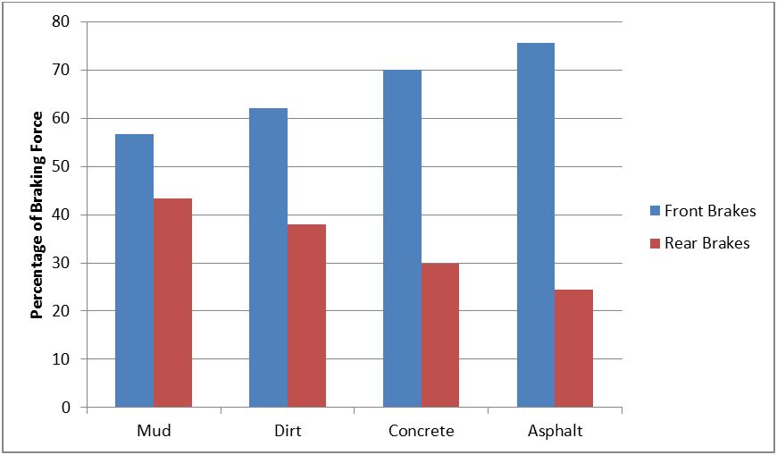
This past year, we discovered just how important testing data is.  Our testing told us to shorten up the car, increase the turning radius, and to change our shock settings for different events.  All of these together definitely made a better car, as we scored better than Cal Poly has in the past nine years.  Testing data helps us confirm (or disprove and change) all of the assumptions we make during our designs.  A senior project of two of the older members left us with a data acquisition system to help us refine our testing techniques in the coming years.  The system can measure: speed, shock travel, front and rear wheel speed, engine rpm, overall accelerations, and steering angle.  Individual wheel speeds, when compared to the speed of the car, give us data about slipping of the tires, a very important aspect of off road racing.  Steering angle and shock travel both are very important for the design of the steering and suspension.  Engine rpm can be used to try to optimize our use of the competition’s regulated engine.  By tuning our CVT (Continuously variable transmission, Blog Entree #1) to maintain the maximum engine rpm at any speed, we can pull as much power out of the engine as possible.

I look forward to the coming year of Baja, acting as the technical director and steering lead, and thank you for reading my blog.  This will probably be my last entree since I was only doing this for my technical writing class, but who knows, maybe I will feel the need to chronicle my adventures as the technical director.  Until then, thanks for reading.

This week: Ergo

When hurdling along at 30 mph, bouncing off of rocks and logs and whatever else the trail throws at you, driver comfort must be taken into account during design.  There are many things about a car that effect driver comfort.  These include several aspects of the steering wheel, pedals, and shock settings.

As far as steering is concerned, wheel position, steering force, and steering range are all important.  The wheel position and angle are mostly personal preference, so we just check the placement with numerous experienced drivers before finalizing it.  Steering forces and the range of steering angle have more significant implications while driving.   Steering force is the amount of strength it takes to force the wheel to turn.  Modern automobiles have power steering to keep steering force low.  For our smaller vehicle, we don’t have to go to this extreme; in fact we have to make sure that there is sufficient steering force for the wheel to give some feedback to the driver.  The range of steering is important, since hand over hand steering, shown in the image below, is not preferred for off-road driving.  When you are being bounced all over the place, the last thing you want is to take your hands off the wheel.  Additionally, this type of car uses its full range of steering much more often than a road vehicle, as it must make tight corners and rapid steering movements.

Source: http://www.nzta.govt.nz/resources/roadcode/gfx/steering-hand-over.gif

Shock settings can greatly affect the comfort of the driver, but potentially at the loss of performance.  The opposite can also be true, for instance, we discovered that very stiff shocks in the rear were good for maneuverability as it made it much easier to slide the rear around tight corners.  The stiff shocks, however, made for a very rough ride on longer drives.  As a result, we had to compromise between performance and comfort for the endurance race.

The positioning of the pedals, as well as the distance they must be pushed, both play important roles in the feel of the car.  Touchy gas or brake pedals can make a car jerky to drive, so the throw distance of the pedals should be designed accordingly.  Additionally, the pedals should be positioned in a way that the driver’s feet and legs are comfortable when the pedals are not being used.  Following this logic, the driver’s leg should be comfortable while not putting any pressure on the brake pedal, as that is the most common position for that leg.

This week: Chassis

According to SAE (Society of Automotive Engineers) rules, each Baja team may use a frame no more than two years.  This is mostly for safety reasons, as the main part of the frame is the roll cage, which protects the driver in a rollover.

By our team’s definition, chassis and frame are somewhat interchangeable.  Technically the chassis is a broader reference to the vehicle, including the frame, suspension, and wheels.  When designing the frame, you are also designing the chassis, since small changes in the frame hugely influence chassis.

This year in our chassis design, the main goals were stiffness, a 50/50 weigh distribution, and a shorter wheelbase.  I will go more in depth into each of these design goals.  Below was the final design of our frame.

Capture
Source: Author

Stiffness, not to be confused with strength – which defines how hard the frame is to actually break – is the ability of the frame to resist deformation, such as twisting or bending.   When your car hits a bump, you want your shocks to be taking the hit.  Because of this, the stiffness of the frame should be ten times the stiffness of the shocks, to make sure that the shocks are actually doing their job.

Weight distribution is a very import aspect of any vehicle, especially a small Baja racer.  Weight distribution simply is where the weight of the car sits on the tires.  Some of the car’s weight will be on the front tires and some on the rear.  A 50/50 weight distribution is an even distribution of 50% of the weight on the front tires and 50% of the weight on the rear tires.  Pushing more weigh towards the rear will help you get more traction in your drive wheels, which could mean better acceleration.  More weigh in the front will help you get more traction with your steering wheels, which could mean better turning performance.  Finding the balance between these is important, and in our testing at the beginning of the year, we found that we could go from our previous 40/60 front/rear ratio to a 50/50 without losing much traction in the drive wheels.

Wheelbase can play a factor in stability and turning radius.  A longer car will be more stable, but will sacrifice a smaller turning radius.  One of the goals for our entire car this year was to get a smaller turning radius to improve our low speed handling, so we shortened the wheelbase of our car by 9 inches.  Additionally we determined that we would not sacrifice stability by shortening it as long as we made no changes to the width of the car.

This week: Competition

This week in Baja, we went to our competition.  This year’s competition was in Bellingham, WA and was comprised of both static and dynamic events.

Thursday and Friday consisted of the static events, including a sales presentation, technical inspection, and design presentation.

The majority of the dynamic events were on Saturday.  These included a brakes test, then hill climb, acceleration, maneuverability, and rock crawl.  Sunday held the main event in store – a four hour endurance race with all the cars on the track at the same time.

Our sales presentation and design presentation both went quite well – we put a lot more focus into these than prior years.  Technical inspection led to a few issues: we had to replace a few frame members and modify our splash shield which keeps gas off of the engine.  After those were fixed, we were allowed to continue on into the dynamic day.

The first thing any car must do in order to be allowed to drive in any other dynamic event is to pass a brake test, in which it must get up to speed, then hit the brakes and lock up all four tires.  Dynamic day yields interesting strategic challenges, since weather can play such a massive role in the performance of our vehicle.  Early in the day it was muddy, and rain was forecast for the afternoon.  We decided to get our runs in at around noon, as it was getting dry, but the clouds were still very threatening.  Below is a picture of us preparing for a very muddy hill climb.

DCIM100GOPRO
Source: Author

Unfortunately for us, the rain never came, so conditions continued to improve through the day, and teams that saved their runs for the end of the day benefited from much firmer ground, making our runs much less impressive.

Even with the worse conditions, we still had an excellent time through rock crawl, good enough to get us 5th in the event (out of 80+).  Below is a picture of our car coming into the hardest corner of the very tough obstacle course.

DSC_9288
Source: Author

As you can see some other teams did not fare quite as well as us during the rock crawl event.  This is one of several cars we saw flip at various sections of the rock crawl, which included climbing over 3 foot logs and up a foot and a half concrete wall.

DSC_9231
Source: Author

The main event, the 4 hour endurance race worth 40% of the points for the entire competition is a challenge to teams’ ability to keep their car on the course.  Based on our past performance, we calculated that each 34 seconds we are off the track equates to 1 out of 1000 possible points for the competition.  This year, we had two minor fixes that took us off the track for a total of about 40 minutes.  Below is a picture of us (car 65) preparing for a pass during the endurance race.

DSC_9459
Source: Author

At the end of the weekend of racing, we got 14th place.  Our goal was to get into the top ten, but if a few more things had gone our way, we feel we would have made it.  If you are interested in seeing more in depth scoring or seeing what other schools we competed against, this link will lead you to a download of the excel file of all the final scores.
http://www.sae.org/servlets/pressRoom?OBJECT_TYPE=PressReleases&PAGE=showCDSNews&EVENT=BAJA&RELEASE_ID=2110

DSC_9940
Source:  Author

This week: Steering

This week in Baja, it was crunch time.  With competition next week, everyone has been working hard to put the finishing touches on the car.  On Thursday, we got a few final parts in, and Friday night was spent on the final assembly of the car.  Today, we got our last day of testing in, and we feel confident in the abilities of our car.  Below is a picture of our competition ready car.  The only task that remains is putting on sponsorship stickers.

Image
Source: Author

Rather than expounding on the difficulties of final assembly, I will go into a brief discussion of steering systems.  Most cars have fairly similar steering systems: the front wheels angle in the direction which you want to turn.  Steering is a bit more complicated, however, as there are several factors which can make the steering system better.  Ackerman steering is the practice of avoiding slip as can be seen below.

Figure 10Green = Inner radiusBlue = Outer radiusRed = Steering angleFigure 11 Turning radius

Source: http://www.beam-wiki.org/wiki/Steering_Techniques

In order for both front wheels to turn freely, without having to skid a bit sideways, is to have both tires travel in a circle about the center of the turning circle.  As you can see in the left picture, this means that the two front tires will no longer be parallel during turning for this to be the case.

An additional concern is called bump steer.  When you are driving along and you hit a bump, if the steering wheel tries to rip out of your hands, then you just experienced bump steer.  In the gif below, the suspension is articulating through its motion.  You can imagine that if bump steer is an issue, then the wheel would be turning slightly throughout the full range of motion of the suspension.


Source: http://en.wikipedia.org/wiki/Multi-link_suspension

An additional example of bump steer can be seen in this video.

Source: YouTube, Peter Basica

This week: Brakes

This week in Baja, we broke the car. Several gears in our reduction gearbox were damaged. This most likely occurred when one tooth broke, then bounced around in the gearbox, breaking other gears. Luckily, they were all smaller gears which can be replaced easily, and there was no additional damage to other gearbox components. The team is now waiting somewhat patiently for the inbound replacements.

Before the gearbox broke, I was preparing to modify the brakes to improve braking performance. To achieve the maximum possible deceleration due to braking, all the tires should be right at the verge of skidding. Anti-lock brakes keep all the wheels right at the verge of skidding. On a small vehicle without anti-lock brakes the ratio of braking between the front and rear tires depends on numerous factors.

The majority of braking is done by the front wheels since the deceleration of the car causes the weight to shift forward.  Anyone who has been in a car that slowed down somewhat quickly has felt these effects.  Due to this, more weight on the front tires means you can try to stop those tires more before you start them slipping.  The figure below illustrates how the rate of deceleration (directly related to the magnitude of friction with the ground) affects the ratio of braking forces required.  These are numbers based off the calculations I did this year to determine the size of brakes required.

Bias Chart

Figure 1.  Contributions to stopping power from front and rear brakes
Source:    Author

If the ratio is not as this figure shows, then one set of tires will start skidding while the others are not sufficiently slowed. The video below shows what happens when your rear brakes start skidding first (also known as rear bias).


Source: Vimeo.com

As you can see, excessive rear balance can cause you to spin out.  On the other hand, excessive front balance will stop you, but only in a straight line.  Your skidding front tires will be unable to steer as they will just keep sliding, regardless of where they are pointing.

All of these descriptions should make you very happy to live in a day where anti-lock brakes keep most of this biasing out of the drivers control, as the anti-lock will keep the one set of wheels from skidding while still allowing the other set to continue increasing the braking force.

If you are interested in learning more about braking, this is an excellent presentation that I looked through a lot when I was initially learning about the surprisingly complicated braking system.
www.sae.org/students/presentations/brakes.ppt

This week: Composites

This week in Baja, I learned about composites.  Composites can be used instead of many different structural members.  On the Baja car, we use composites to replace what would usually be large sheets of aluminum or steel.  Instances of this include body panels, the floor, and a front skid plate.  The main benefits we look for here are weight savings while at the same time improving the strength and stiffness of the components.  Strength of a material refers to the ability to be hit without breaking, while stiffness refers to the ability to get hit without bending (or deflecting).  For the floor and skid plate, we used a foam core to greatly increase stiffness.  In the past, the floor has been a solid plate of either steel or aluminum.  The steel skid plate at the front of the car from last year weighed 8 pounds where this year’s composite plate weighs less than 2 pounds, and can still take the same impacts without deflecting.

The advantages of the composites are clear, so why isn’t everything made of composites?  The cost of materials as well as the difficulty to manufacture the molds required to form the fabric-like carbon fiber or fiberglass into the desired shape make composites less feasible for most applications.  The manufacturing process for composites, known as a lay-up, can be a lengthy process.  First you must make a mold, which for our low budget, could be shaped foam, or in an industry setting, a machined metal mold.  Next, you have to determine what the layers of your composite are going to be, and what order they will be in.  Fiberglass and carbon fiber are the two main components in the composites we use.  Carbon fiber is much stronger and stiffer, but tends to be vulnerable to rubbing and friction, so it is usually surrounded with layers of fiberglass.  Additionally, composites are stronger in some directions than others – this is determined by the direction of the weave.  The fibers are woven in a perpendicular pattern; layers should be offset by 45 degrees to obtain the maximum possible strength from the composites.  The layers are impregnated with resin which ultimately hardens to give you the final product.

Below is an image of a sheet of carbon fiber that has just been layered with resin.  You can see the weaves of the fibers as well as get an idea for how fragile composites are around the edges before they harden with resin.

carbon_fiber_sheet

Source: http://volvospeed.com/~volvo/Pics/Mods/carbon_fiber_sheet.jpg

This week, my task was to make a cover for the steering rack to keep a barrier between the driver’s feet and the moving parts of the rack.  This image shows the steering rack when it is uncovered.  The steering wheel attaches to the part in the middle to turn and slide the horizontal rod side to side, turning the wheels.

IMAG1326Source: Author

I shaved a foam mold to cover the rack, leaving a hole for the steering column which will stick out.  Here the mold is, covering the steering rack.

IMAG1327Source: Author

Next, I layered the fiberglass and carbon fiber onto the mold, coating each layer with resin before proceeding.  After all the layers were laid up, a vacuum bag was put over the whole thing to help force the resin into the fibers and get rid of air bubbles.

IMAG1338
Source: Author

Finally, after 8 hours of setting, the final product could be removed from the mold.  All that remains to do is cut off the excess around the edges and drill the holes needed to bolt it on.  The picture below shows the finished piece next to the mold which was wrapped in aluminum tape to keep the resin from sticking.

IMAG1341
Source: Author

This week: Suspension

This week in Baja, we had to get the car ready for technical inspection.  What that means is that all of the rules of SAE, the society of automotive engineers who sponsors the competition, must be met by our car.  The remaining items for us include a lot of small things, including car numbers, as well as various other aesthetic parts.  All of the sub team leads are double checking all facets of their systems for any way that the car will not be acceptable according to SAE rules.  The first thing that happens at competition is technical judging, not only to make sure that the car is safe to drive, but also to score our car based on our design decisions.

On the note of design decisions, it is easy to get lulled into the idea that our car is the only concept of vehicle that can be realized.  Upon arriving at competition, you rapidly realize how many design variations there can be.  Variations in suspension alone make no two cars alike.  The most basic option is double A-arm suspension, as pictured below.

Source: http://www.carbibles.com/suspension_bible.html

The part with the circular hole on the right side is called the upright.  The upright is the part that attaches the suspension linkages and also where the wheel attaches.  The idea of any suspension is to have the wheel move along a predictable arc when the suspension articulates from hitting a bump.  Bearings attach the A-arms to the upright so the wheel can stay somewhat vertical as the suspension moves up and down.  This introduces the concept of dynamic suspension geometry, where an angle of the tire, called camber, can help dig in during turns.  Suspension theory can get very complicated; the list of contents on the Wikipedia page for suspension is intimidating enough to make a young engineer question his career choices.  Thought that is the case, the basic idea is relatively simple: to have the wheels able to cushion the impact of bumps on the road.  Additionally, the suspension should react desirably to weight transfers during turning, accelerating, and braking, as should sound familiar to anyone who has driven a road car.

Wikipedia Suspension Article
http://en.wikipedia.org/wiki/Suspension_(vehicle)

This week: Transmission

This week in Baja we managed to keep the car mostly intact.  With three weekends remaining to get the car ready for competition, we are starting to feel the pressure.  Weekly testing has been going well: we drive until something breaks.

Each week we take the car out to Pozo, an off-road recreational vehicle area about an hour northeast of San Luis Obispo.  Recently, we have been testing the car for the endurance race at competition, which requires that the car be able to drive for 4 hours straight, where points are awarded based on total distance traveled.  Our goal for each session at Pozo is to complete 4 hours of uninterrupted drive time.  We have completed the 4 hours a few times, but not with the consistency we want to see for the actual competition.

The car currently utilizes numerous parts from last year’s car, which has caused reliability issues.  One in particular, the CVT, or continuously variable transmission, has been failing recently.  The CVT acts similarly to the chain on a bike, except it varies the sizes of the gears based on the current rpms.  You can see this action below – also note that it can run at every ratio between the highest and lowest possible.  The idea is, a well tuned CVT will make your car permanently in the optimal gear for the current speed.  On our car, this makes for a very smooth acceleration to a respectable top speed of 35mph, without the need to shift gears.  We already have the new CVT; we just need to make a few small modifications to it to work with our current engine setup.

Source: http://www.howstuffworks.com/cvt2.htm

Last week, we had a huge crash during testing, requiring repairs to our frame as well as both the front and rear suspension.  The team worked hard and managed to get the car back up and running within 5 days: quite the impressive feat partway through the first week of a new quarter.

As the brakes system lead, my job this week was to finally install the rear brakes.  For several weeks, we had been testing with only front brakes on the car.  This is not as unsafe as it may sound, as about 70% of braking is done by the front wheels because of weight transfer forward during deceleration.  With my official duties all but completed, next week will undoubtedly have something new in store for me.  There are always more tasks: the to-do list never ends.